Creating Custom Solutions with Sikla's Standard Configurations
January 7, 2025
The modular nature of Sikla makes nearly any design possible, and it's an ideal material for creating easily adjustable customized solutions. While the sky is the limit as far as creativity goes, a Sikla solution is typically made up of the same six construction configurations, all leveraging Sikla's 14 standard connection types.
Standard Sikla Framo Configurations
No matter the requirements or challenges of your solution, a customized Sikla build will most likely be made up of a combination of six different configurations of siFramo materials. Each configuration can be further customized using different beam types depending on the load requirements of your solution.

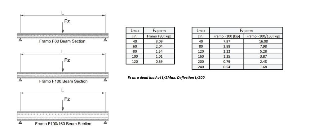
1. Simply Supported Beam
This basic configuration can use siFramo F80, siFramo F100, or siFramo F100/160 beam sections.
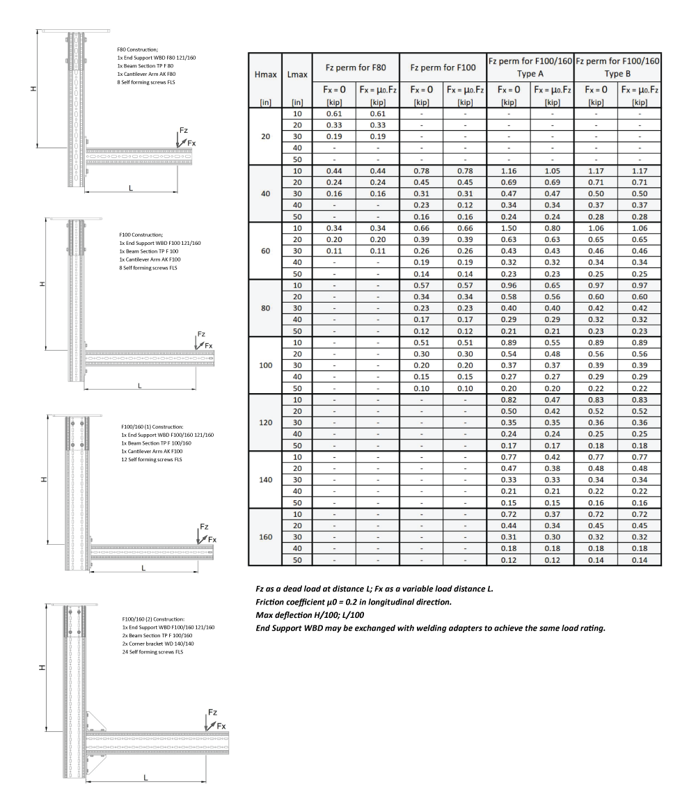
2. L-Construction
This configuration can use F80 and F100 beam sections and features two different configurations when using F100/160 beam sections.
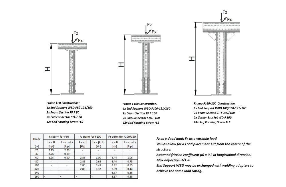
3. T-Construction
This configuration can use F80, F100, or F100/160 beam sections.
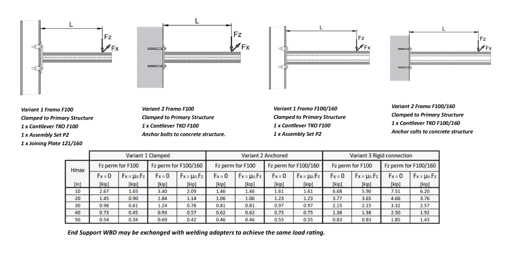
4. Cantilever Construction
This configuration has two options each when using either F100 or F100/160 beam sections, dependent on how the beam is attached to the primary structure.
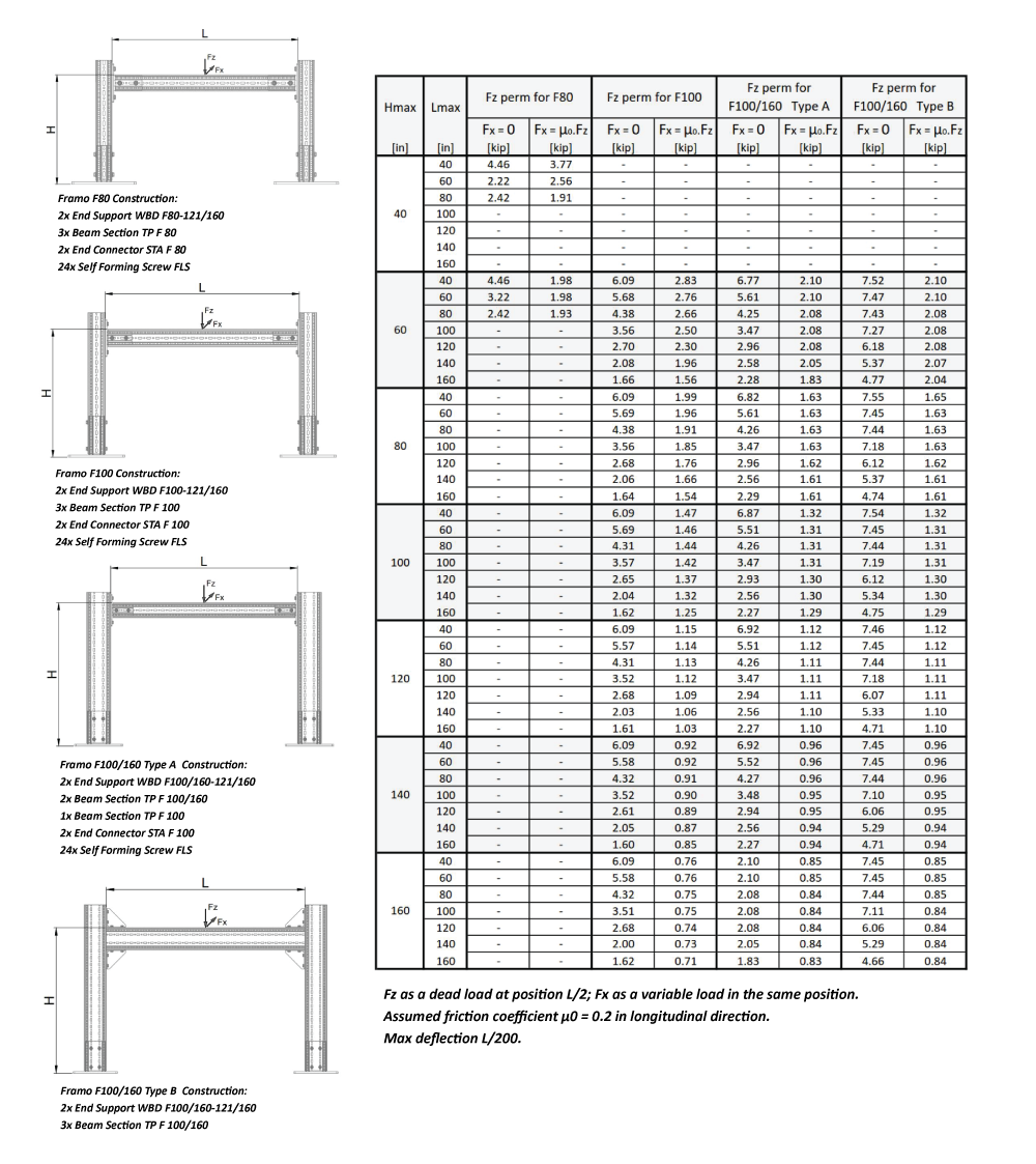
5. H-Construction
This configuration can use F80 and F100 beam sections and features two different configurations when using F100/160 beam sections.
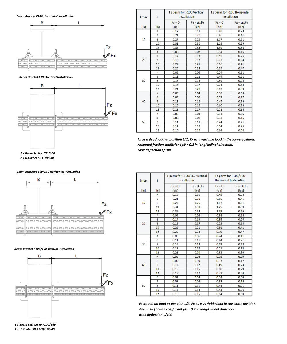
6. Beam Bracket Connections
This configuration can be installed horizontally or vertically with F100 and F100/160 beam sections.
Standard Sikla siFramo Connections
Each of the above configurations require one or more of siFramo's standard connections, as illustrated in the Sikla Assembly Guidelines. Familiarizing yourself with the basics of these connections, as well as Sikla's self-forming screw, can allow for quicker construction.
siFramo End Connector Connections
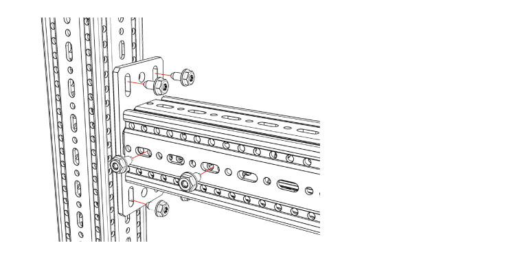
End Support STA
Notes:
- FLS screws attached to internal connector should be in pairs on opposite sides of siFramo section
- FLS screws attached to internal connector preferably mounted on main axis of imposed force
- Maximum of 3/8" between end of section and face of plate
End Support STA E (offset)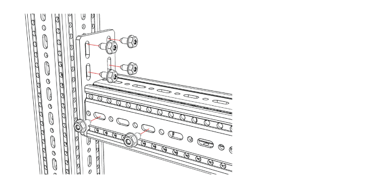
Notes:
- FLS screws attached to internal connector should be in pairs on opposite sides of siFramo section
- FLS screws attached to internal connector preferably mounted on main axis of imposed force
- Maximum of 3/8" between end of section and face of plate
End Support STA F100 – 100/160
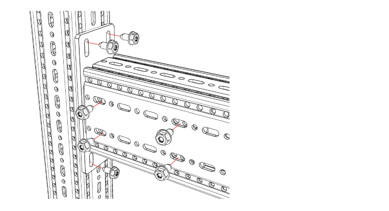
Notes:
- FLS screws attached to internal connector should be in fours on opposite sides of siFramo section
- Maximum of 3/8" between end of section and face of plate
End Support STA F100 – 100/160 E (offset)
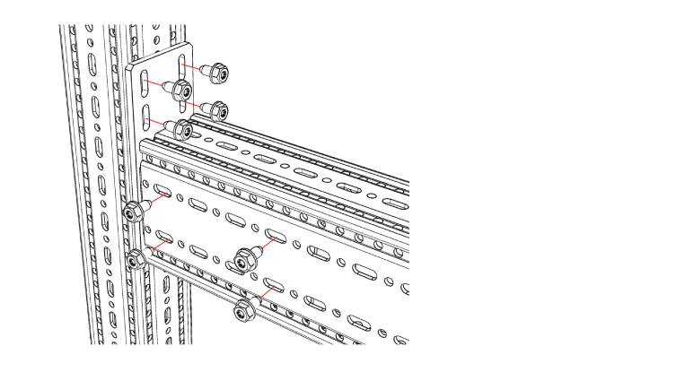
Notes:
- FLS screws attached to internal connector should be in fours on opposite sides of siFramo section
- Maximum of 3/8" between end of section and face of plate
End Support STA F80 - 30
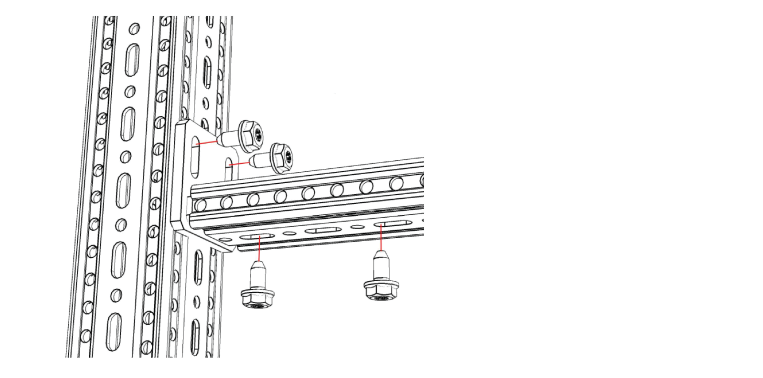
- Beam Section Sizes: F80 / F30
- FLS Screws Required: 4
Notes:
- FLS screws attached to the internal connector should be as far apart as possible
- Maximum of 3/8" between end of section and face of plate
Corner Bracket Connections
Corner Bracket WD 140/140

Notes:
- Two brackets required per connection, as shown
Pivot Joint Connections
Pivot Joint GE
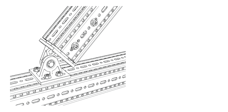
Notes:
- FLS Screws attached to internal connector should be in fours on opposite side of siFramo section
- FLS screws attached to internal preferably mounted on main axis of structure
- Maximum of 3/8" between end of section and face of plate
Pivot Joint GE (with baseplate)
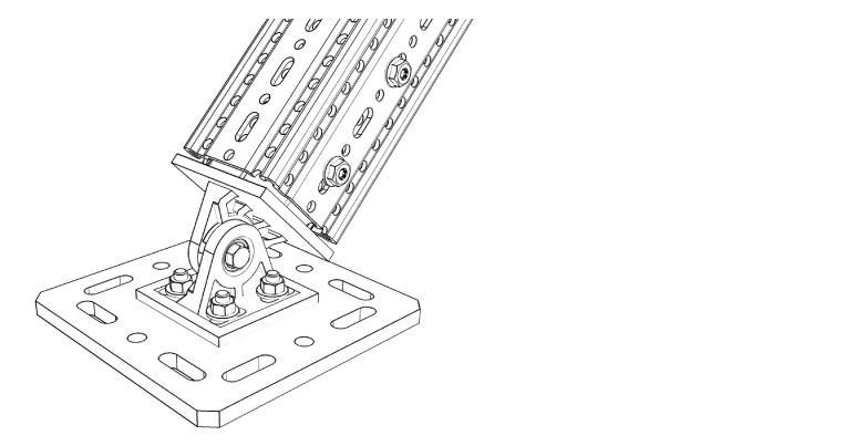
Notes:
- FLS screws attached to internal connector should be in fours on opposite sides of siFramo section
- FLS screws attached to internal preferably mounted on main axis of structure
- Maximum of 3/8" between end of section and face of plate
- Variety of baseplates available for clamping or anchoring to structures
U-Holder SB Connections
U-Holder SB F30 / F80 / F100 / F160
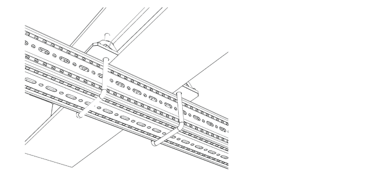
Notes:
- Two variations available: -16 and –40 for flange thicknesses up to 16 mm and 40 mm
- To be used in pairs
Beam Section Holder Connections
Beam Section Holder TPH F80 / F100 C
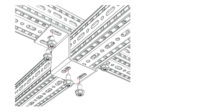
Notes:
- Bracket to connect intersecting beams
Beam Section Holder TPH F80 / F100
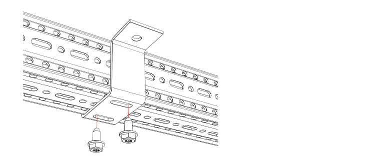
Notes:
- Bracket to connect to concrete surfaces / cast-in concrete channels / drilled steelwork sections
Bracing Arm Connections
Bracing Arm SKO F100
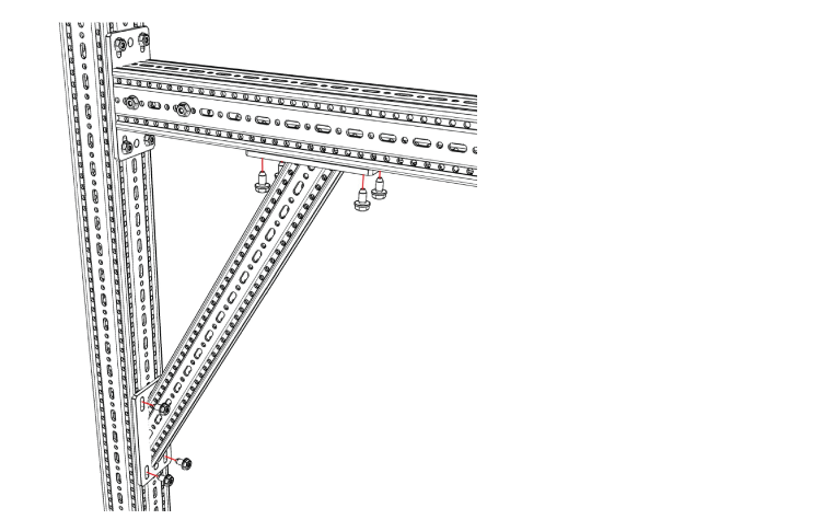
- Beam Section Sizes: F100
- FLS Screws Required: 8
Notes:
- Four FLS screws on each plate
- Suitable anchors may be used to fasten left hand side plate to another building surface if required
siFramo Footplate Connections
WBD F80 / F100
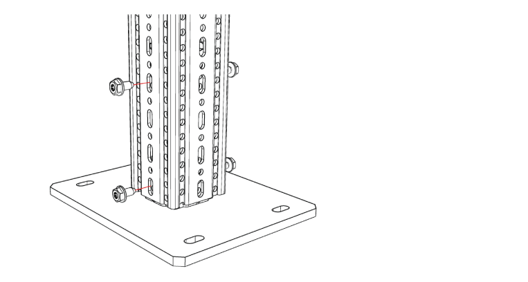
Notes:
- FLS screws attached to internal connector should be in pairs on opposite side of siFramo section
- FLS screws attached to internal preferably mounted on main axis of structure
- Maximum of 3/8" between end of section and face of plate
- Fixed to building structure using suitable heavy duty anchors or frictional connection via Sikla Assembly set
WBD F100 / 160
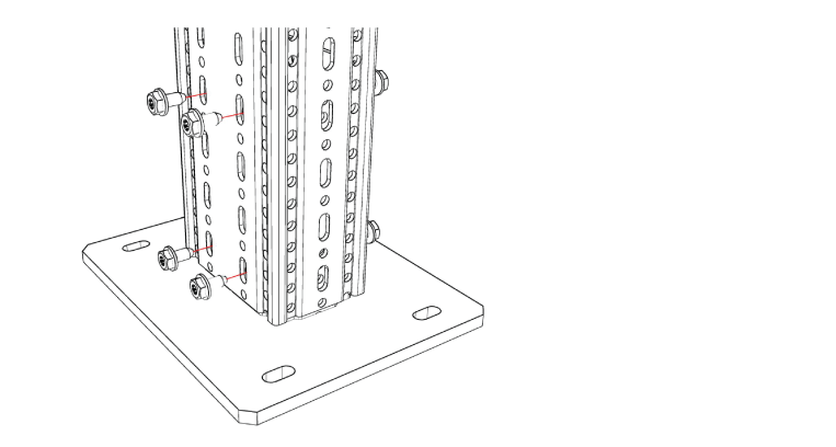
- Beam Section Sizes: F160
- FLS Screws Required: 8
Notes:
- FLS screws attached to internal connector should be in fours on opposite side of siFramo section
- FLS screws attached to internal preferably mounted on main axis of structure
- Maximum of 3/8" between end of section and face of plate
- Fixed to building structure using suitable heavy duty anchors or clamped connection via Sikla Beamclamp set
Sikla siFramo Working Loads
Sikla working loads vary widely and are dependent on the configuration, beam sections and connections used, and the four typical loading scenarios found when supporting piping, ducting, electrical services, and equipment:
- Distributed load
- Point load
- 2 point loads
- 3 point loads
While there are quick reference charts available to help determine appropriate working loads for various configurations, with the number of variables found in these scenarios, we recommend working with a trusted Sikla partner like Unistrut Midwest.
Unistrut Midwest has been designing, sourcing, prefabricating, and installing custom Sikla solutions for years. We have the experience and expertise to create the solution you need.

